Search
Search Results
SearchAMI Modem Card ,
find 8 items
- Sort by
- Most recent
- Popularity

Training
Tool
Learning
Watch time - 3:23
Demonstrate how to use the ICP Programming Tool to generate a programming file, and use the PC to save the firmware to the USB/SD storage device, insert the USB/SD storage device into Nu-Link2-Pro, and then connect the target chip, press the trigger button to complete offline programming.
-
For more information, please visit Nuvoton Technology Website: https://bit.ly/3hVdcmC
Buy now: https://bit.ly/3bk0AD8
Contact us: SalesSupport@nuvoton.com
#en #Tool #Training #Intermediate #Learning

Training
Tool
Learning
Watch time - 3:24
Hello everyone I am Chris, the Field Application Engineer from Nuvoton Technology.
Today I will introduce the programming and debugging tool, called NuLink-Gang, and NuLink2-Pro. And I will show you in what kind of situation you can utilize the tools.
During system development, Nuvoton provides three IDE interfaces: KEIL, IAR, and NuEclipse for user to develop source code.
When programming the Chip, Nuvoton provides ICP programming Tool in PC and the debugger Nu-Link2-Pro for users to perform debugging and programming function.
User who uses all of the Nuvoton Nu-Maker boards series can develop through the Nu-Link2-Me debugger and programmer; it’s attached to the board.
During the mass-production stage, there are 2 modes for programming the target chip. One is online programming and the other is offline programming.
At first, in online programming mode, user can use ICP programming Tool and a Nu-Link2-Pro to program a target chip. Besides, if it needs to program several chips at one times, the Nu-Link Command Tool supports program multiple develop board by several Nu-Link2-Pro.
Nu-Link2-Pro also supports drag-and-drop Flash programming. User can intuitively complete the programming action.
Nu-Link2-Pro
In offline programming mode, user can pre-store the programming file in SPI flash, USB flash drive, or SD card. When user wants to program the target chip, pressing the programming button on Nu-Link2-Pro to complete the programming action.
If it needs a large number of ICs to be programming, it recommends using the Nu-Link-Gang programmer. Nu-Link-Gang programmer can perform offline programming on four different chips at a time, significantly increasing the programming efficiency. Besides, Nu-Link-Gang programmer can also use the control bus to connect with an automatic programming machine for automatic programming.
In the system upgrade, Nu-Link2-Pro also provides five standard communication interfaces such as SPI, I2C, UART, RS485, and CAN for transmission, which is convenient for users to upgrade the system.
That’s all for the introduction of Nuvoton’s programming and debugging tool, NuLink-Gang, and NuLink2-Pro. Thank you for watching it. If you want to know more details, please contact us! Thank you.
#Tool #Training #Learning #Intermediate #en
-
For more information, please visit Nuvoton Technology Website: https://bit.ly/3hVdcmC
Buy now: https://direct.nuvoton.com/numaker-m251sd
Contact us: SalesSupport@nuvoton.com
Training
Tool
Learning
Watch time - 5:0
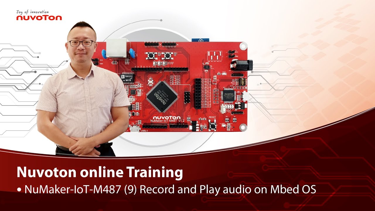
Hello everyone, I am Morgan, the principal engineer of Nuvoton Technology. Today, I will show you how to record and play audio with Mbed OS on NuMaker-IoT-M487 development board.
Open Chrome browser, and enter the URL https://ide.mbed.com to use the Mbed Online Compiler.
After log in, make sure that NuMaker-IoT-M487 board already selected in the upper right corner. If not, please refer Nuvoton IoT Tutorial series “Get Started with Mbed OS” which has a detailed description of how to add a board.
Click the “New” on the left of menu bar, a “Create new program” window will be displayed.
You can see that the Platform has been set to NuMaker-IoT-M487. In the Template, select the "NuMaker audio playback" for this tutorial. Then click OK.
Now you can see that the sample code has loaded on the page.
The sample code has three functions:
1. Record 10 seconds sound and save to Micro SD card
2. Play sounds stored in Micro SD card
3. Loopback. Record sound and play it immediately.
Click main.cpp to open it. Then scroll down to line 421. You can see the functions calls here. It set to loopback only.
Let’s do a little modification. Hit a key on console to start record 10 seconds then play it, and then do loopback.
printf("Press a key to start recording 10 seconds...");
getchar();
demo_record();
demo_play();
demo_loopback();
Save it and click “Compile” to build the code.
Compilation takes a while, please wait.
After the compilation is completed, “Success” will appear in the compile output window.
The browser downloads the binary firmware file directly after a successful compiling. It will be saved in a default download folder. In Chrome, you can click download file and select “Show in folder”.
Please plug an earphone commonly used for mobile phone in headphone jack on NuMaker-IoT-M487 board. For demonstration, we use a headphone splitter cable to connect a microphone and a speaker. Do not put the microphone and speaker too close to avoid feedback howling. Then connect the USB port to your computer and make sure the onboard LED lights up.
Back to the folder you just download the binary firmware file (NuMaker-mbed-AudioPlayback-example.NUMAKER_IOT_M487.bin). Drag and drop the file to NuMicro MCU drive.
You will see the copying progress dialog box.
Please find the virtual COM port assigned for NuMaker-IoT-M487 in Device Manager. In the demonstration, the “Nu-Link Virtual Com Port” is COMx.
Then use your favorite terminal tool. Here we use Putty. Open the COMx port with 9600 baud rate.
And no flow control settings. Then “Open” it.
Press “Reset” on board to run the firmware again.
Press a key on terminal to start record.
Speak for about 10 seconds, then your voice will be played.
That’s all for this tutorial. Thank you for watching.
Welcome to subscribe to our channel.
If you want to get more information, please contact us “SalesSupport@nuvoton.com”
-
For more information, please visit Nuvoton Technology Website: https://bit.ly/3hVdcmC
Buy now: https://direct.nuvoton.com/tw/numaker-iot-m487
Contact us: SalesSupport@nuvoton.com
#tool #training #learning #intermediate #en

Training
Tool
Learning
Watch time - 3:55
Hello everyone, I am Morgan, the principal engineer of Nuvoton Technology. Today, I will show you how to use SD card with Mbed OS on NuMaker-IoT-M487 development board.
Open Chrome browser, and enter the URL https://ide.mbed.com to use the Mbed Online Compiler.
After log in, make sure that NuMaker-IoT-M487 board already selected in the upper right corner. If not, please refer Nuvoton IoT Tutorial series “Get Started with Mbed OS” which has a detailed description of how to add a board.
Click the “New” on the left of menu bar, a “Create new program” window will be displayed.
You can see that the Platform has been set to NuMaker-IoT-M487. In the Template, select the "NuMaker SD-File-System with SD mode" for this tutorial. Then click OK.
Now you can see that the sample code has loaded on the page. LittleFS uses less memory, supports power failure protection. However, LittleFS is different from the FAT file system, so after uses littleFS, the SD card will be formatted as LittleFS. The sample code uses FAT file system as default.
Just click “Compiler” to build the example.
It is in compiling, please wait a moment.
After the compilation is complete, “Success” will appear in the compile output window.
The browser downloads the binary firmware file directly after a successful compiling. It will be saved in a default download folder or the folder based on your browser setting. In Chrome, you can click download file and select “Show in folder”.
Please insert a micro SD card into the card slot on the back of NuMaker-IoT-M487 board, then connect the USB to your computer and make sure the onboard LED lights up.
Let’s back to the folder you just download the binary firmware file (NuMaker-mbed-SD-FileSystem-example.NUMAKER_IOT_M487.bin). Drag and drop the file to NuMicro MCU drive.
You will see the copying progress dialog box.
Please find the virtual COM port assigned for NuMaker-IoT-M487 in Device Manager. In the demonstration, the “Nu-Link Virtual Com Port” is COMx.
Then use your favorite terminal tool. Here we use Putty. Open the COMx port with 115200 baud rate
And no flow control settings. Then “Open” it.
Press “Reset” on board to run the firmware again.
You can see the messages on terminal while accessing SD card.
That’s all for this tutorial. Thank you for watching.
Welcome to subscribe to our channel.
If you want to get more information, please contact us “SalesSupport@nuvoton.com”
-
For more information, please visit Nuvoton Technology Website: https://bit.ly/3hVdcmC
Buy now: https://direct.nuvoton.com/tw/numaker-iot-m487
Contact us: SalesSupport@nuvoton.com
#tool #training #learning #intermediate #en
Training
Tool
Learning
Watch time - 8:37
NuMaker-IoT-M487 (5)
Connect to Pelion Device Management on Mbed OS
Hello everyone, I am Morgan, the principal engineer of Nuvoton Technology. Today, I will show you how to connect to Pelion Device Management with Mbed OS on NuMaker-IoT-M487 development board.
Because the demonstration needs to store certificate, a MicroSD card is required.
Open Chrome browser, enter the URL https://cloud.mbed.com/quick-start
If you didn’t use Pelion Device Management before, you need to activate your Mbed account to access Pelion. Click the “Activate your free access”. Then log in your Mbed account.
Click “Activate Pelion Device Management account“…
Select the “Start the Connect Tutorial”
Then scroll down to select NuMaker-IoT-M487 (WiFi)
--After selected, scroll down and click “Get started”--
If you have completed previous tutorial, the NuMaker-IoT-M487 board has been selected in your Mbed account.
Please click the “2.2” to import the Pelion Connect Tutorial into your Online Compiler.
It shows the import dialog box, please click Import.
Wait for a moment while importing the sample code.
Click “mbed-os-example-pelion” project name,
Then click “Pelion Device Management” on menu bar, select “Manage Connect Certificates” in pull-down menu to create a Pelion certificate.
You need to provide API key. You can create a new one here.
Log in your mbed account.
Accept
Then click New API key
Assign an API Key name
Click Close
After created an API key, back to online compiler,
Then click Manage Connect Certificate again.
API Key automatically filled here.
Click OK.
Click “Create”, then assign a name for the certificate.
Click OK.
Click the certificate just created to select it, then click OK.
The online compiler will automatically update source code with the selected certificate.
Click “Pelion Device Management” on menu bar again, select “Apply Update Certificate”. An “Update Certificates” dialog box appears. Create it.
Click Download Private Key and save it.
Please make sure that NuMaker-IoT-M487 board already selected in the upper right corner. If not, please refer Nuvoton IoT Tutorial series “Get Started with Mbed OS” which has a detailed description of how to add a board.
In order to use Wi-Fi, you have to configure SSID and password to match your Wi-Fi access point setting.
In the mbed_app.json file, the default Wi-Fi security set to WPA and WPA2 in “nsapi.default-wifi-security” field. Please modify the field “nsapi.default-wifi-ssid” to your Wi-Fi SSID
Then modify “nsapi.default-wifi-password” to your Wi-Fi password.
Click on “Compile” to build it. Have to wait for a while.
Then you can see the last message is “Success!” at the bottom of this page.
The browser will download the binary firmware file directly after a successful compiling. It will be saved in a default download folder or the folder based on your browser setting. In Chrome, you can click download file and select “Show in folder”.
Then we connect the NuMaker-IoT-M487 USB port to your computer and make sure the onboard LED lights up.
Let’s back to the download folder where you can see the binary firmware file (mbed-os-example-pelion.NUMAKER_IOT_M487.bin). Drag and drop the file to NuMicro MCU drive.
You will see the copying progress dialog box.
Please find the virtual COM port assigned for NuMaker-IoT-M487 in Device Manager. In the tutorial, the “Nu-Link Virtual Com Port” is COMx.
Then use your terminal tool. Here we use Putty. Open the COMx port with 115200 baud rate, 8 bits, 1 stop bit, none parity, and no flow control settings.
Then “Open” it.
Press Reset button on board to run again.
You can see the connection messages printed on terminal. It shows the board’s IP address obtained from the Wi-Fi access point, and the Endpoint Name.
Then you can see the device resource in Pelion Device Management Portal.
Log in Pelion Portal with the same Mbed account.
Click Device directory. Find the device ID which should be registered state.
Click the Device ID, it shows the Device details.
Click RESOURCES, find the resource 3200/0/5501. Click the resource.
Now, you can press keys in terminal to increase the counter. Or the counter automatically increase 1 by one second. The demo code also updates the counter to Pelion. You will see the value change in the graph.
That’s all for this tutorial. Thank you for watching. Welcome to subscribe to our channel. If you want to know more information, please contact us at SalesSupport@nuvoton.com
-
For more information, please visit Nuvoton Technology Website: https://bit.ly/3hVdcmC
Buy now: https://direct.nuvoton.com/tw/numaker-iot-m487
Contact us: SalesSupport@nuvoton.com
#tool #training #learning #intermediate #en

Training
Tool
Learning
Watch time - 8:36
Hello everyone, I am Morgan, the principal engineer of Nuvoton Technology. Today, I will show you how to use 4G LTE or NB-IoT with Mbed OS on NuMaker-IoT-M487 development board.
This tutorial needs a cellular expansion board to work with NuMaker-IoT-M487 development board. You can purchase the 4G LTE expansion board, RF-EC21A, on Nuvoton Direct (https://direct.nuvoton.com/communication-module/). Please install your 4G LTE SIM card in the mini SIM card slot on the back, and install the antenna at the MAIN connector on the front of the board.
Although there is an NB-IoT expansion board, it requires an NB-IoT SIM card. Using LTE is more convenient. Just use your own LTE SIM card which has data plan.
Then install the expansion board to the Arduino UNO connector of the NuMaker-IoT-M487 development board.
Because the power consumption of the 4G LTE module is higher, it is not enough to supply power from USB only. You need to plug in the 5V/2A power supply. If you use NB-IoT module, no additional power supply is needed.
We used “New” to select a template to create a new project. This time, we use the example on GitHub to create a new project. The URL of template used for this tutorial is https://github.com/OpenNuvoton/NuMaker-mbed-Cellular-example
In chrome browser, enter the URL https://ide.mbed.com to use Mbed Online Compiler environment.
After you log in, make sure that NuMaker-IoT-M487 board already selected in the upper right corner. If not, please refer Nuvoton IoT Tutorial series “Get Started with Mbed OS” which has a detailed description of how to add a board.
Click the second option “Import” on the upper left.
In the Import Wizard, click “Click here”
On the “Source URL:”, enter the tempalte URL https://github.com/OpenNuvoton/NuMaker-mbed-Cellular-example . Then move mouse cursor to “Import Name:” and click it, the Project name will be automatically fill in. Then click “Import” button.
Now you can see that the sample code has loaded. Depending on the cellular module used, the configuration may need to be modified. Click on “Readme.md” to open it. It lists configurations for supported cellular modules.
Because the tutorial uses RF-EC21A expansion board which includes a Quectel EC21 LTE module, let’s check and modify the configuration in mbed_app.json file.
Click the “mbed_app.json” file to open it. It is a JSON file to customize compile time configuration parameters in Mbed OS. The “*” (asterisk) in “target_overrides” session indicates all development boards are applicable. You can set in the designated board session, so the settings are only applicable to the specified board.
The default mbed_app.json file in the example has configured for RF-EC21A. Such as,
"target.network-default-interface-type" has set to "CELLULAR" for cellular connection.
Both "lwip.ppp-enabled” and "lwip.tcp-enabled" set to true.
Use generic AT3GPP driver for RF-EC21A ("GENERIC_AT3GPP.provide-default": true)
And the RF-EC21A UART connects on Arduino D0/D1 ("GENERIC_AT3GPP.tx": "D1" and "GENERIC_AT3GPP.rx": "D0")
When your SIM card installed in your mobile phone, you can find the APN, username and password settings in your mobile phone. Or contact your telecom operator to get this information. In the example, APN has set to “internet”, no username, and no password. (Move mouse cursor around these settings)
The final setting to check is PIN code. In the example, the setting is no PIN code. If your SIM card has PIN code, for example 1234, please set it like this “\”1234\”” (Move mouse cursor around the setting)
Save it then build it.
It is in compiling, please wait a moment.
Then you can see the last message is “Success!”.
The browser will download the binary firmware file directly after a successful compiling. It will be saved in a default download folder or the folder based on your browser setting. In Chrome, you can click download file and select “Show in folder”.
Then we connect the NuMaker-IoT-M487 USB port to your computer and don’t forget to plug in external 5V power supply.
Please find the virtual COM port assigned for NuMaker-IoT-M487 in Device Manager. In the demonstration, the “Nu-Link Virtual Com Port” is COMx.
Then use your favorite terminal tool. Here we use Putty. Open the COMx port with 115200 baud rate, 8 bits, 1 stop bit, none parity, and no flow control settings. Then “Open” it.
Let’s back to the download folder where you can see the binary firmware file (NuMaker-mbed-Cellular-example.NUMAER_IOT_M487.bin). Drag and drop the file to NuMicro MCU drive.
You will see the copying progress dialog box.
You can see the connection messages printed on terminal. It shows that the board creates a TCP connection to server “echo.mbedcloudtesting.com”, send 4 bytes data and get the data back from server.
That’s all for this tutorial. Thank you.
For more information, please visit Nuvoton Technology: https://bit.ly/3hVdcmC
Buy now: https://direct.nuvoton.com/tw/numaker-iot-m487
#tool #training #learning #intermediate #en

Watch time - 4:59
Secure Smart Metering Communication Reference Design
Hi everybody, today we are going to introduce a reference design of Smart-Metering communication card based on NuMicro M2351 Series microcontroller. You can find useful security features based on the Arm Cortex-M23 CPU core with Nuvoton’s in-house technology integration.
The auto-metering is an infrastructure for automatic, remotely, wire or wireless meter data reading. It’s highly possible to be intervened if there is no security mechanism. That is a very typical IoT security issue in the IoT era.
In many countries, there are a lot of Auto-Metering Infrastructure (AMI) projects being undertaken by main electricity power companies worldwide. Most projects start from upgrading the communication modem cards as the first step rather than retiring the meters. The modem card can play as a gateway to monitor the incorrect device operation and data transmission security. Issues of modem card security are covering:
First, a limited performance due to crypto computation efficiency
Second, speed limitation due to interface choice
The third, cost burden due to extra hardware modules for different communication protocols
Nuvoton’s reference design of Secure Smart Meter Communication is an end-to-end security solution for AMI. With the collaboration with SPI-Korea, the solution incorporates a lot of advantages such as TrustZone security for firmware, a range of interfaces for device communication, secure over-the-air firmware update, and remote management. With the complete hardware specification of M2351, a security software company, SPI-Korea, can easily implement their secure AMI solution for modem card which connects meters and cloud servers. M2351 also contributes the crypto acceleration during the cryptographic computing in order to save CPU time for different communication protocol modules by its powerful hardware functionalities during message transmission outside of a microcontroller unit.
SPI-Korea has developed a range of Armv8-M TrustZone based technologies. Her expertise covers Boot Manager, Key Manager, and Device Manager, which is very useful for microcontroller security and certainly shows the stability of a microcontroller device. Also, they are certified by Korea Electricity Company. We hope this successful experience can be further adopted in other areas worldwide because it’s a secure, accurate and environmentally safe solution for AMI.
This slide is a picture for SPI-Korea AMI modem card design. NuMicro Family microcontrollers can be utilized for designs of auto-metering infrastructure devices. We start from AMI modem card and we are confident to support meters of any next-generation of AMI. We now integrate M23-based microcontroller with M4-based or Arm9-based microcontroller as a proposal for next-generation modem card of Korea AMI and we hope to provide high-performing cost-effective solution for all AMI devices in the future.
-
For more information, please visit Nuvoton Technology Website: https://bit.ly/3hVdcmC
contact us: SalesSupport@nuvoton.com

Watch time - 3:12
本方案使用 NuMicro M480 高效能 M4 微控制器,搭配 emWin library 進行 GUI 圖像化人機介面設計,將結果顯示在 2” OLED 上。NuMicro M480 系列微控制器是新唐的最新產品,透過這個系列產品高達 192 MHz 的強大運算能力和多達 160 KB 的 SRAM,並且搭配 2 吋 OLED 螢幕,來達到流暢地解碼及播放 GIF 動態影像,那這個方案包含了三大重點:
第一點:我們使用了新唐 M480 高效能微控制器,透過高速 SPI 控制 OLED 來顯示炫麗的動態效果
第二點:本方案已內建 GIF 解碼和多種字型的 Library,如果有其他字型需求,可以透過新唐字型轉換工具載入其他字庫,再加上 emWin Library 的使用,快速開發完成高質感使用者介面。
第三點:本方案可以應用於有顯示功能需求的產品,如電競主機板,可以高效地動態顯示溫度、風扇轉速和硬碟狀態等
-
更多產品資訊,請至新唐科技網站 https://bit.ly/3hVdcmC
聯絡我們:SalesSupport@nuvoton.com
----
Today we are going to introduce our reference design OLED Display with GIF Format Decode featuring the NuMicro M480 series microcontroller. As you can see, the microcontroller controls the 2-inch OLED screen and GIF files can be played on it. The M480 series runs up to 192 MHz with 512 KB embedded Flash memory and 160 KB embedded SRAM. The high-performance MCU decodes GIF motion graphics smoothly.
There are three major features about this reference design:
First: We use the Nuvoton M480 high-performance microcontroller to control the OLED through high-speed SPI to showcase dynamic effects.
Second: This solution has built-in GIF decoding and various font libraries. If there are other font requirements, you can load other fonts through the Nuvoton font conversion tool, and use the emWin Library to develop a high-quality user interface quickly.
Third: It can be applied to products requiring display functions, such as e-sports motherboards, which can dynamically display temperature, the speed of the fan and the status of the hard disk.
The OLED device has a 2-inch OLED screen with a resolution of 256*64. There is an SD card slot underneath, which obviously is for data storage and the storage status is shown on the OLED screen. The right side, there is a high-speed USB for PC connection as a flash drive. A headphone jack is on the left, I’m sure you all know how it works.